slotcars, slot car, technical information, technical guide, Pro Slot, Camen, Slick 7, PK, GT-1


|
|
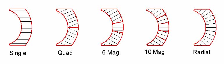
Question: How can you attach pinions on an open car without spinning? Answer: There are two methods that have been sucessful. Method 1) This is the most reliable and foolproof method. This is recomended for the M515 straight pinned pinion only. Grind a groove in the shaft for the pin, located so that the pinion is centered on the spur. Slide the pinion on so that the hole aligns with the notch. Bend an L in a piece of M636 wire, slide one end through the hole. Carefully bend the other end so that the piano wire form a U, trim it so that the ends of the wire point away from the motor and are flush with the end of the pinion. Either apply flux and solder to the end of the motor shaft and pin wire or use two part epoxy. When it is time to remove the pinion use a gear puller, this will break the wire into three pieces, make sure that you remove these pieces from the can and magnet so that they don't get caught between the arm and magnet and take out your magnets. Check the pinion for cracks around the hole, if cracks are found discard the pinion, otherwise reuse it. Next time install a new piece of M636 wire and repeat the steps above. Method 2) Completely remove any old solder from the motor shaft and tin using use M618 high melting point solder, flux and then slide on a new M543 or M542 pinion using an iron (or torch), apply heat until you see the solder on the inside of the pinion melt. If there is no solder on the inside remove the pinion apply a greater quantity of solder and install pinion again. Remove gear with gear puller. Question: How do you install the new M629 long life motor ball bearings? Answer: The hole in the endbell must be enlarged to .175 to allow clearance for the machined bearing retainer. The side where you do not see the balls goes into the endbell away from the arm. On the can side the side where you do not see the balls goes towards the pinion. When the bearings are installed in the motor and the arm is installed the balls will be shielded and not visible. Question: How are radial magnets different from singles or multi magnets? Answer: This is best answered with the following diagram. Most magnets are made from straight line oriented material because of the expensive tooling required for radial magnets, however radial magnets achieve the best possible orientation.
Question: What is the recommended break in procedure for motors? Answer: First contour the end of the brushes with a M270 brush radius tool. You can spin the shaft with a M413 grinder/drill tool. If you have a diamond tool try to avoid ones which leave a very smooth surface as this will hinder break in. The purpose of the contouring is to correct for any imperfections in the alignment of the brush hoods. After installing the arm break in the motor according to the following schedule: G7 1.2 v 10 minutes, 2 volts 20 minutes, 3 volts 10 minutes, G27 1.5 volts 10 minutes, 2.5 volts 20 minutes, and 3.5 volts for 10 minutes, G-20 1 volts 10 minutes, 2 volts 20 minutes, and then 3 volts 10 minutes, Box stock, G12 & G-15 3 volts 20 minutes, and then 4 volts 10 minutes, Competitor and D can motors 20 minutes at 4 volts. The purpose of break in is to run in the brushes at reduced speed compared to what they would see on the track until they are fully seated. This prevents destructive arcing when full power is applied and the result is a faster, longer running motor and more cuts on your comm. Do not exceed the maximum voltage indicated. Zinging a motor up to 8-12 volts will often cause motor damage because with no load on the motor much higher rpm can be reached then is obtained under load on the track (also avoid lifting the rear tires off the track and punching the trigger). While the motor might seize, broken wires, stretched comm segments, cracked phenolic, damaged ball bearing, bent lam stacks, and cracked arm epoxy, can and will occur. The result will be a slow, weak performing motor. The damage is cumulative and will get worse every time excessive voltage is used. Question: My controller trigger operation has become gritty, how do I fix it? Answer: Apply a small amount of Vasoline or oil on the wiper board where you see the track of the wiper button. Controller need lubrication too! You will need to clean the space between the brake pad and the first band occasionally or metal particle may build up and your car may go without you pulling the trigger. Question: My car moves slowly even when the trigger is not pulled. What can I do? Answer: Over time metal particles can build up in the space between the brake pad and the first power band. If enough particles build up they may conduct electricity. You may notice smoking or even glowing between the brake pad and the first band. To fix this use a Q-Tip and lighter fluid or rubbing alcohol wipe the space clean. If metal particles have been allowed to build up for too long the circuit board material may carbonise. In that case wiping may not be enough, and you may need to scrape the carbon off the plastic before the controller will work correctly. This problem may occur especially if you oil the switch block. If you do not oil your switch block it may become sticky and the wiper button may not return all of the way to the brake position causing loss of brake, adding lube will fix this but it is necessary to occasionally clean the space between the brake pad and first band.. Question: What can I do to improve the balance of the tire/axle/gear assembly? Answer: Use tires axles and gears which have a balanced design. Also use spurs and pinions which are made to a high degree of precision. Koford tires are made using hollow set screws and the set screw hub diameter is designed so that when used with Koford flatted axles the weight of the set screw is offset by the material removed in grinding the flat and the assembly is balanced. Grinding axles with flats located 120° apart does not improve the balance. Since the set screws are not in the same plane it does not matter what the angle of one is to the other. The axle assembly will be in static balance but not in dynamic balance so there will be no improvement. For smooth operation each assembly must be designed so that each one individually is in balance. Question: What should I look for to achieve a smooth gear mesh? Answer: The first step to ensure that solder does not get in the teeth of your pinion. The best way to do this is to use Black Diamond pinion which are coated with an ultra low friction non solderable coating which prevents solder form sticking. The second is to buy gears which are accurately made. The most accurate gears on the market today are Koford Selected pinion and spurs which are obtained by 100% testing all of the gears we make with a commercial gear tester in accordance with AGMA standards and selecting only those with the very lowest Total Composite Error. Note that gear accuracy is not determined by and cannot be measured from the runout of the gear OD or the gear edge. The meshing part of the gear is the curved side of the tooth. It is in the form of an involute which has the property when mated with another involute of rolling rather then sliding contact. This results in a gear mesh which is 98% or better efficient with almost no losses. A gear with no run out of the outside or edge often will be noisy while one with noticeable run out can be dead quiet. Gear vibration can result due to improper curvature of the teeth, improper spacing of the teeth (too close or to far), and out of round character of the teeth. This can only be measured with a commercial gear testing machine. Question: Some arms I have run have soft arm shafts which wear out after a few races. I have heard about drill blank shafts but I hear that they still rust and stick in ball bearings and are hard to solder to. What type of shafts do Koford armatures use? Answer: All Koford arms and also our 3/32 axles feature a surface which is superior to drill blanks. Soft shafts (piano wire shafts) measure about Rc50, drill blank shafts measure Rc62, while Koford arm shafts and axles have a surface hardness of Rc70. Not only is the shaft hard so there will be negligible wear but the surface has very low friction and will not rust. The surface also has excellent solderability to help prevent pinions from spinning. Question: What are the advantages of short vs. long chassis? Question: How can I avoid damaging the plating on an aluminum chassis when I solder and unsolder the motor? Answer: The first thing is to use 60:40 silver solder (Koford M444) or
regular 60:40 solder to install your motor (also use this solder
to attach body mounts, and install ball bearings, but use regular
silver solder (Koford M333) to attach your pillow blocks and top
and bottom braces. The second thing is to never force the motor
out, use only light pressure or you will damage the plating. The second thing is to use rosin paste flux when changing motors and to attach lead wires so as to not corrode the chassis and motor.
Question: What is the advantage of brush heat transfer compound "brush cream" and how do I apply it to motor brushes? Answer: Like the name suggests brush heat transfer compound keeps your brushes and comm cool which helps to prevent comm damage and reduces comm and brush wear. The part number is M295. To use it first clean off the tip of a screwdriver and use it to mix the heat transfer compound. Holding the brush between your fingers (or using tweezers) coat the four exposed outside surfaces with compound except leave 1/16 inch uncoated on the side next to the comm. Make sure that the end of the brush touching the comm is uncoated, as well as the end touching the comm. Slide the brush in. There should be a small amount of excess squeezed out between the brush hood. If there is a large amount you can use a pin to remove the excess. If there is not any compound squeezed out, remove the brush, apply more compound and try again. Question: How do I glue in magnets in a multimagnet set up? Answer: This is easiest if you use a magnet height that matches the can you are using. For example .480 tall 6 or 20 magnets with a .480 tall can. It is also easier if you use the open can for .380 long magnet opens, the G27 can for .400 long G27 magnets etc. as these cans have magnet stops to locate the magnet lengthwise. Otherwise you will have to set the magnet position using calipers. Clean the inside of the can with a rubber wheel (like from a dremel etc), do this by hand not in a dremel. You want the inside of the can clean and shiney. You want to make sure not to remove plating, just clean off the surface. Then take a Q tip dip it in solvent and wipe off the can and magnets. This might take a couple of Q-tips. Be sure not to put the dirty Q-tip back into the clean solvent. Let the solvent evaporate. For the solvent an electronics type chlorinated solvent would be best, if you don't have that MEK or Acetone will work. Apply M345 epoxy to the can and put in the first segment, apply M345 to the inside edges of the magnets so that they are bonded to each other. Push the magnets back against the stop, push the center segments back against the can just to make sure that they are seated, use calipers to align the magnets height wise with the can. Let the magnets sit for an hour. Use the calipers again to make sure the magnets are in the right position in case they have moved a bit. Place in a cold oven with the bearing end of the can up, set the time for 1-1/2 hours at 180C (356F). Have the set up zapped and you are ready to grind. The outer segments come zapped and the centers are unzapped and this is the way you should use them, you will find that the centers are much easier to handle (and much less likely to break) if you don't zap them. |